

Our News
Contact Us
- Tel:0086-135 8771 2673
- Tel:0086-135 8771 3265
- Email:[email protected]
- Address:No.666 East Jiaotong Rd.,Wu'niu Street,Yongjia,Wenzhou,Zhejiang,China
Time Delay Relays: Types, Functions, and Applications
News | Aug 21,2024
This article thoroughly explores the functionality and applications of time delay relays, highlighting their critical role in various industrial and commercial settings. By understanding the types and practical uses of these relays, you can better grasp how to implement them effectively in systems requiring precise timing control, such as motor start control, lighting, and HVAC systems.
Reading this article will provide valuable insights into the selection and application of time delay relays, ensuring safe and efficient operations. Whether you’re dealing with complex automation systems or simple electrical circuits, this knowledge will help you prevent equipment damage, enhance reliability, and optimize system performance.
Key Points
- Time Delay Relay: Controls timing in circuits.
- Ensures safe, precise operations.
- Adjustable timing: From milliseconds to minutes.
- Types: On-delay, off-delay, one-shot, cyclic.
- Used in motors, lights, HVAC, safety systems.
- Critical for preventing equipment damage.
- Wiring and dimensions vary by model.
- Common in industrial and commercial applications.
What is a Time Delay Relay?
A time delay relay is a specialized kind of relay utilized in electric circuits to present a hold-up in between the application or removal of power and the operation of the relay calls. Unlike conventional relays that respond virtually immediately to adjustments in input, time relays are created to manage the timing of their action, making them important in applications where timing precision is essential.
Time hold-up relays are built to manage functions such as starting electric motors, controlling lights systems, or sequencing occasions in commercial procedures. They make sure that particular operations do not occur as well swiftly, consequently avoiding potential damage to devices or guaranteeing safe procedures in automated systems. The hold-up can be configured for different periods, varying from nanoseconds to a number of minutes, relying on the certain demands of the application.
In method, these relays are often used to take care of events such as:
| Application | Time Delay Relay Function |
|---|---|
| Motor Start Control | Delays motor begin to stay clear of power surge |
| Illumination Systems | Transforms lights on/off after an established delay |
| Heating Elements | Guarantees regulated heating by delaying component activation |
The style of a time hold-up relay generally includes a timing circuit and a common relay. The timing circuit is responsible for developing the delay, and it can be based upon electronic, pneumatic, or mechanical systems, relying on the relay type. When the collection time expires, the relay activates or deactivates its get in touches with, therefore completing or disrupting the circuit.
How Does a Time Delay Relay Work?
A time delay relay (TDR) operates by managing the timing of the relay’s get in touches with, either delaying their opening or closing after a certain trigger event. The core function of a TDR hinges on its capacity to manage the time period in between the application of a stimulus and the resultant activity. This accurate timing ability is crucial in different electrical and commercial applications.
At the heart of a TDR is an internal timing system, which can be based upon digital, pneumatically-driven, or mechanical systems. When a launching signal is received, the timing mechanism starts counting down according to the pre-programmed delay period. This hold-up duration can vary from nanoseconds to numerous mins, relying on the design and application requirements.
The relay contacts, which are the key elements that open up or close the circuit, will just transform state after the hold-up period has actually expired. As an example, in a generally open TDR, the calls will continue to be open up until the hold-up duration ends, whereupon they will close, completing the circuit. Conversely, in a generally closed TDR, the calls will certainly remain closed till the delay time ends, creating them to open and break the circuit.
The hold-up time is usually adjustable, permitting users to adjust the timing to match details needs. This modification can be done with dials, digital interfaces, or even software program, depending on the sort of TDR being made use of. Additionally, some TDRs provide multiple timing functions, such as on-delay and off-delay, providing additional convenience in their operation.
In recap, a Time Delay Relay works by leveraging a controlled timing system to manage the procedure of its get in touches with, making sure that the circuit is triggered or deactivated precisely at the wanted time. This functionality is essential for applications where timing accuracy and integrity are vital.
Different Types of Time Delay Relays
Time delay relays are important elements in different electrical and digital systems, giving accurate control over the timing of operations. These relays can be found in a number of types, each designed to satisfy specific demands and applications. Understanding the different sorts of delay time communicates is crucial for selecting the right one for your task.
On-Delay Timer Relays
On-delay timer relays are the most common type. When the control signal is used, the relay awaits a predefined delay period before triggering the result. This kind is extensively used in applications where a delay is required before starting an action, such as in motor control circuits.
Off-Delay Timer Relays
Off-delay timer relays run oppositely to on-delay timers. When the control signal is removed, the relay continues to maintain the output active for a defined hold-up period before shutting off. This type works in scenarios where an action requires to be maintained for a specific duration after the control signal is turned off.
One-Shot Timer Relays
One-shot timer relays give a single output pulse of a specified period when triggered. These relays are helpful in applications requiring a short-lived action, such as in industrial automation systems where a solitary pulse can initiate a sequence of procedures.
Cyclic Timer Relays
Cyclic timer passes on alternate between on and off states for defined durations, creating a duplicating cycle. This kind is suitable for applications needing regular procedures, such as in flashing lights or interval-based control systems.
Multi-Function Timer Relays
Multi-function timer relays deal several timing functions within a single unit, supplying versatility for different applications. These relays can be set up for on-delay, off-delay, one-shot, and cyclic operations, making them flexible for intricate control systems.
Star-Delta Timer Relays
Star-delta timer relays are specialized for motor beginning applications. They regulate the transition from celebrity link to delta connection in electric motor windings, minimizing the beginning existing and guaranteeing smooth motor start-up.
| Kind Of Time Delay Relay | Function | Typical Applications |
|---|---|---|
| On-Delay Timer Relay | Delays the activation of the result after the control signal is used | Motor control circuits, lighting systems |
| Off-Delay Timer Relay | Keeps the output energetic for a hold-up period after the control signal is gotten rid of | Safety and security systems, delay-off illumination |
| One-Shot Timer Relay | Offers a solitary output pulse of a defined period | Industrial automation, sequence control |
| Cyclic Timer Relay | Alternates between on and off states for specified durations | Flashing lights, interval-based control |
| Multi-Function Timer Relay | Offers several timing functions in one system | Complex control systems, functional applications |
| Star-Delta Timer Relay | Controls the transition from celebrity to delta link in electric motor windings | Electric motor starting applications |
Each kind of time hold-up relay offers a special objective, and choosing the ideal one depends upon the specific requirements of your application. Whether you require accurate timing control for commercial automation, electric motor beginning, or security systems, comprehending the various kinds of time delay relays will certainly help you make an informed decision.
Practical Applications of Time Delay Relays
Time Delay Relays (TDRs) are indispensable parts in various industrial and commercial applications because of their capability to control the timing of electric circuits. Their adaptability and dependability make them suitable for a wide variety of usages. Listed below, I will certainly outline several of the most common and critical applications where TDRs play a pivotal function.
Industrial Automation
In commercial automation, Time Delay Relays are thoroughly utilized to handle the sequencing of operations. For circumstances, in conveyor belt systems, TDRs can be used to ensure that products are relocated a timed sequence, protecting against jams and making certain smooth procedure. They additionally play a crucial duty in device start-up and shut-down sequences, where accurate timing is critical to prevent devices damages and ensure safety.
Heating and Cooling Systems
Heating, Ventilation, and Air Conditioning (HVAC) systems profit considerably from using Time Delay Relays. They help in controlling the time intervals for activating and off compressors, followers, and various other components. This not only improves the performance of the system but additionally prolongs the life expectancy of the tools by protecting against brief biking and minimizing wear and tear.
Illumination Control
Time Delay Relays are generally used in lights control systems to manage the timing of lights in industrial buildings, road lights, and even in property setups. For instance, they can be set to turn lights on and off at certain times, thus preserving power and decreasing expenses. In emergency situation lights systems, TDRs ensure that lights remain on for an established period throughout a power outage.
Motor Control
In motor control applications, TDRs are made use of to manage the begin and stop features of motors. They can supply delayed start to stop inrush currents that can possibly harm the motor or trigger circuit breakers to trip. Additionally, TDRs can be used to carry out staggered starting of multiple motors to lower the total lots on the electric system.
Safety and Security Systems
Time Delay Relays are integral to numerous safety systems. In fire alarm systems, TDRs can be made use of to delay the activation of alarms to enable verification of the alarm system problem, decreasing the event of incorrect alarms. In elevator control systems, TDRs guarantee that doors continue to be open for an enough time to enable guests to get in and leave safely.
Refine Control
In procedure control settings, TDRs are used to handle the timing of numerous procedures. As an example, in chemical processing, they can manage the timing of blending, heating, or cooling down stages to make certain that reactions take place under optimal conditions. This exact control is vital for maintaining item quality and functional efficiency.
The useful applications of time delay relays are huge and varied, demonstrating their vital function in boosting the effectiveness, security, and reliability of numerous systems throughout various markets.
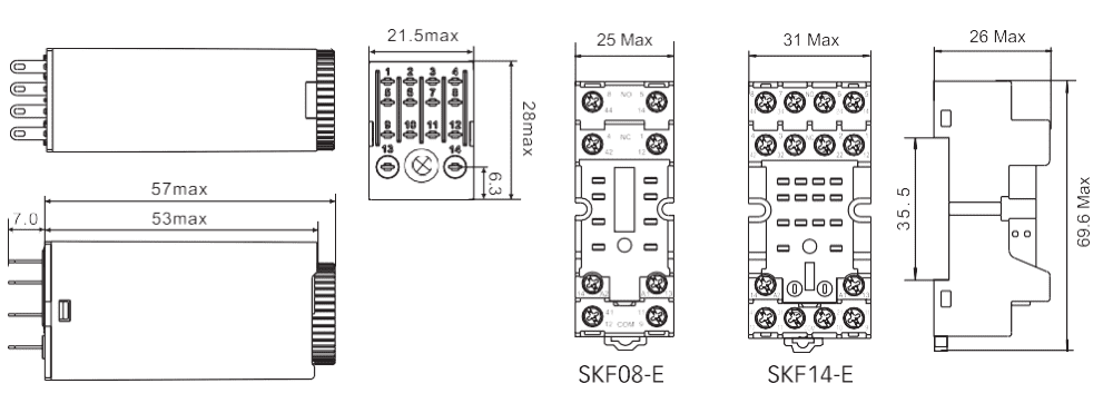
Dimensions of Time Delay Relays
When selecting a time delay relay for your application, comprehending the measurements is vital. The dimension and form of the relay can substantially impact its setup and performance within a system. Commonly, the dimensions of a time delay relay are established by its style, which can differ relying on the kind and performance it gives.
The Majority Of time delay relays are made to be small to fit within conventional electrical panels or enclosures. Nonetheless, the precise dimensions can vary based upon the producer and model. Typically, these relays are available in both DIN rail mountable and panel mountable arrangements. Below is a basic synopsis of the normal measurements:
| Mounting Type | Height (mm) | Width (mm) | Depth (mm) |
|---|---|---|---|
| DIN Rail Mountable | 70-90 | 22.5-45 | 60-100 |
| Panel Mountable | 80-120 | 30-60 | 70-130 |
The size of the relay ought to be matched to the area available in your control cabinet or system. In addition, you should think about the relay’s weight, as this can influence the convenience of setup and the suitability for details applications.
Another factor to consider is the spacing between terminals, specifically if you’re collaborating with a high-density setup. Appropriate spacing makes certain ease of wiring and decreases the danger of short circuits or connection mistakes. Below is a regular incurable spacing standard:
| Terminal Type | Spacing (mm) |
|---|---|
| Screw Terminal | 5-10 |
| Plug-in Terminal | 7-12 |
In summary, the measurements of a time delay relay are a key factor to consider during the option process. They affect not just the setup but additionally the operational effectiveness of the relay within your system.
Time Delay Relay Wiring Diagram
When it concerns circuitry a time delay relay, comprehending the layout is critical for correct installment and capability. A wiring layout provides a graph of the electric links and the parts involved in the relay circuit. Right here, I will assist you through the important elements commonly located in a time delay relay circuitry diagram.
Components of the Wiring Diagram
A standard time delay relay wiring diagram consists of several crucial parts:
- Power Supply: This is the resource of electric power, typically represented by a symbol representing air conditioner or DC supply.
- Relay Coil: The coil is the part of the relay that, when stimulated, turns on the relay system. It is commonly marked with a sign that suggests its link to the power supply.
- Get in touches with: These are the changing aspects that open or close the circuit. They are usually displayed in both their regular (de-energized) and turned on (invigorated) states.
- Timing Circuit: This part of the layout stands for the parts that manage the hold-up time, such as resistors, capacitors, or integrated circuits.
Actions to Read a Time Delay Relay Wiring Diagram
To effectively read and carry out a time delay relay wiring representation, follow these actions:
- Identify the Power Supply: Locate the source of power on the diagram and note whether it is a/c or DC. Make sure that the voltage ranking matches your application.
- Locate the Relay Coil: Find the relay coil and trace its connections to the power supply. This will certainly aid you comprehend how the coil is energized.
- Recognize the Contacts: Examine the relay calls and their settings. Identify which contacts are usually open (NO) and which are generally shut (NC). This will help you figure out how the relay will certainly regulate the circuit when triggered.
- Analyze the Timing Circuit: Study the timing circuit elements and their links. This section will reveal you just how the hold-up time is established and adjusted.
Typical Wiring Configurations
There are numerous typical circuitry arrangements for time delay relays:
- On-Delay Relay: In this configuration, the relay triggers after a preset delay once the coil is invigorated. The electrical wiring layout will certainly show the timing circuit connected in such a way to postpone the activation of the calls.
- Off-Delay Relay: Here, the relay shuts down after a preset hold-up once the coil is de-energized. The representation will illustrate the timing circuit keeping the relay activation for a particular period after power is eliminated.
- Interval Relay: This kind of relay activates for a predetermined interval once the coil is energized. The electrical wiring layout will depict a timing circuit that regulates the duration of the relay activation.
By meticulously researching and understanding the electrical wiring layout, you can make sure the appropriate installment and operation of your time delay relay. Proper electrical wiring is vital to harness the complete possibility of these versatile gadgets in various applications.

Conclusion
A time delay relay is a crucial component in different applications, giving exact control over timing series. These tools play a crucial function in guaranteeing that electric circuits run in a secure and coordinated way. By including a hold-up in the relay’s activation or deactivation, it is feasible to prevent breakdowns and boost the reliability of facility systems.
The appropriate selection and application of a time delay relay can significantly impact the efficiency of a system. Variables such as the kind of relay, its timing range, and its voltage requirements must be very carefully thought about. This ensures that the relay does as anticipated in its intended application, whether it be in commercial automation, HVAC systems, or various other electric systems.
Comprehending the requirements and dimensions of a time delay relay is additionally vital. This consists of not just its physical size yet likewise its electrical qualities, such as current score and voltage tolerance. These variables should line up with the requirements of the system to avoid prospective issues during operation.
Electrical wiring a time delay relay properly is essential for its proper functioning. A detailed circuitry diagram need to constantly be referenced to guarantee accurate connections. This avoids usual troubles such as incorrect timing or perhaps damage to the relay or the system it regulates.
In general, time delay relays are vital in modern-day electric and electronic systems. They offer exact control over timing, assisting to ensure that procedures are carried out safely and efficiently. Their flexibility and integrity make them a recommended choice in numerous applications, underscoring their significance in the field of electric design. If you have any questions about our products, please feel free to contact us at [email protected].
--- END ---