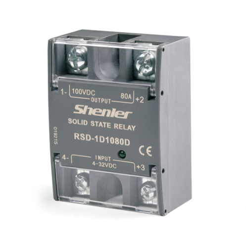
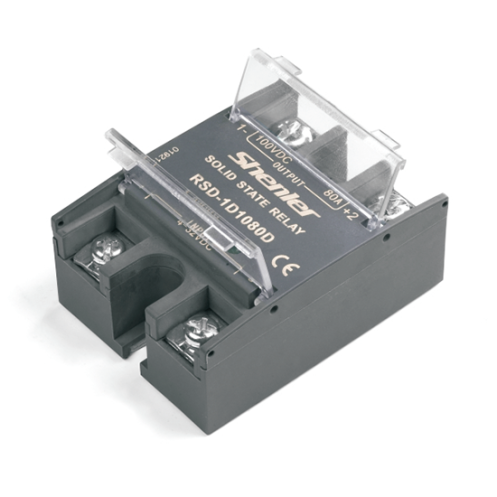
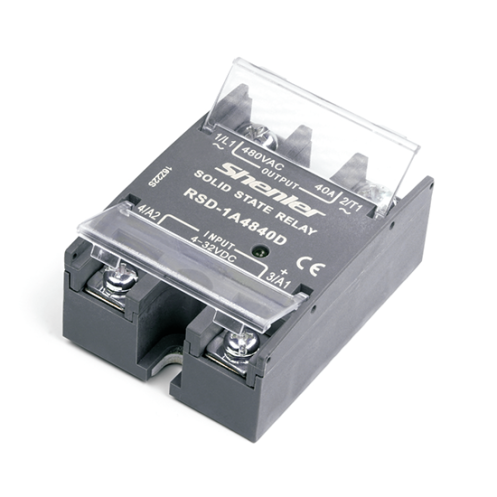
RSD Series AC DC Solid State Relay
Features
Designed with 1 N/O SPST DC output.
With long service life, no contact, no spark.
Having MOSFET output, fast switching response.
Equipped with imported optocoupler isolation.
Owning wide control voltage range and LED indicator.
Available in optional IP20 protective cover and panel mounting.
Widely used in DC heating, DC power supply, DC valve, DC motor, and etc.
 Download Request A Quote
 Share Our Social
Current level selection:
Considering the load surge current and relay overload capacity, to make the relay work with long life and high reliability, it is recommended to select the current magnification corresponding to the load type in the table below.
| Load type | Resistance | Electric heating wire | Incandescent lamp | transformer / electromagnet | Motor |
| Power factor | 1.0 | 0.7 | 0.5 | 0.4 | 0.2 |
| Magnification | 1.5multiple | 2multiple | 2.5multiple | 4multiple | 7multiple |
Note:
1. Please be sure to set fuse, air circuit breaker and other protective equipment on the power side to prevent short circuit.
2. When connecting inductive load, be sure to reverse parallel freewheeling diode at the load end (see “Terminal configuration and wiring diagram” for specific connection method)!
3. M5 screw and spring washer are used with 2N.m torque. After 3 hours of use, tighten it once with the same torque. To ensure the close contact and firm installation between the base plate of the solid-state relay (hereinafter referred to as the product) and the heat sink.
4. The product wiring shall be standard wire, and the cross-sectional area can be selected according to 5-8A per square millimeter. The terminal shall ensure that the wiring is firm. Loose wiring will lead to abnormal heating and damage to the product. In case of high temperature and high humidity environment, conductive compound shall also be coated on the connection part.
5. The input terminal is standard M4 screw, and the wiring tightening torque is (1.2-1.4) N.m. the output terminal is standard M5 screw, and the wiring tightening torque is (1.5-1.8) N.m.
6. Please do not connect the current above the rated specification. Otherwise, it may cause abnormal heating of the product.
7. Do not apply voltage exceeding the rated value on the input circuit and output circuit, and pay attention to the wrong connection of positive and negative polarity, otherwise the product will fail or burn.
8. Requirements for installatio: it shall be installed vertically on the chassis with good ventilation conditions, and make full use of the heat dissipation conditions of air convection.When two or more products are installed side by side, an appropriate large gap shall be reserved.
9. When the ambient temperature of the product is high, please refer to “Performance curve” to check the current temperature curve for derating. When it exceeds 60 ℃, air cooling is needed to ensure that the temperature of the product bottom plate does not exceed 80 ℃.
10. Before installation, maintenance and other operations, be sure to cut off the power supply in case of electric shock!
Characteristics:
Input parameter(Ta=25℃):
| Control voltage range | 4~32VDC |
| Must turn-on voltage | 4VDC |
| Must turn-off voltage | 1VDC |
| Control current range | 6~20mA |
Output parameters(Ta=25℃):
| Part No. | RSD-1D06XXD | RSD-1D10XXD | RSD-1D20XXD | ||||||||||
| Load voltage range | 7-48 | 7-75 | 7-120 | ||||||||||
| Maximum load current(A) | 20 | 40 | 60 | 80 | 100 | 20 | 40 | 60 | 80 | 100 | 20 | 40 | 60 |
| Maximum surge current(Apk,@10ms) | 110 | 160 | 200 | 260 | 300 | 90 | 140 | 180 | 220 | 280 | 80 | 160 | 200 |
| Maximum PWM(Hz) ★ | 900 | 700 | 700 | 500 | 500 | 900 | 600 | 600 | 400 | 400 | 800 | 600 | 400 |
| Maximum conduction voltage drop(V) | ≤1 | ≤1.2 | |||||||||||
| Maximum off-state leakage current(mA) | ≤0.3 | ||||||||||||
| Minimum load current(mA) | ≥2 | ||||||||||||
| Maximum conduction time(ms) | 1 | ||||||||||||
| Maximum off time(ms) | 1 | ||||||||||||
Other parameters(Ta=25℃):
| Dielectric withstand voltage (50/60Hz) | Between Input and Output | 2500Vrms |
| Input/Output to base | 2500Vrms | |
| Insulation resistance(@500VDC) | 1000MΩ | |
| Operating temperature range | -30℃~+80℃ | |
| Storage temperature range | -40℃~+100℃ | |
| Operating ambient humidity range | 5~85%HR | |
| Cooling mode | Install the heat sink and add fan-forced cooling when the temperature exceeds 60℃ | |
| Weight Approx | 90g | |
| ★ Note: For the PWM rating, a voltage of at least 8 Vdc must be applied to the control input. | ||


